‘Y’ Thermal Bridging
Thermal bridging happens when one area of a building has a significantly higher level of heat transfer than the other parts. It is commonly found at junctions and connection details between building elements. Within buildings and constructions, it is important for thermal bridging to be managed effectively, as it can lead to as much as 30% of a building’s total heat loss.
Find out more about thermal bridging below.
What is Thermal Bridging?
Thermal bridging can be described as the movement of heat across an object which is more conductive than the other materials that are around it. As a result of this, the conductive material creates a path of least heat resistance. When thermal bridging occurs in buildings, it can be a cause of significant heat loss, which can result in unnecessarily high energy bills due to reduced energy efficiency. Therefore, it is highly recommended that during initial design or refurbishment, areas of risk are mitigated with thermal bridging solutions that will increase the property’s thermal efficiency. Designers should consider how best to avoid issues associated with condensation created through cold surface spots and the areas surrounding the construction elements which form the bridge. This condensation can lead to mould growth within buildings, which can cause significant risk to occupants’ health and wellbeing.
When it comes to measuring thermal bridging and the effects it has on a building, Y-values and U-values are usually discussed. The thermal bridging Y-Value is a measure of the overall heat loss expected from all of the thermal bridges identified in a design. Each individual thermal bridge is represented by a Psi value. The U-value can be defined as a measurement of how effective the elements of a property’s building fabric are as insulators i.e. a calculation of the wall, floor, roof or window’s ability to prevent heat transfer from the inside and outside of the building.
Classifications of Thermal Bridging
Repeating Thermal Bridges
This type of thermal bridging follows a pattern and it is thus repeated over an area of the property’s thermal envelope. Repeat thermal bridges are often described as common and predictable, nevertheless, they can still cause significant heat loss in a building. Examples of this are ceiling joists in cold pitched roofs, steel wall ties which are used in masonry cavity wall construction and a break caused by timber framing when there is insulation between the studs. On occasion, the impact of these types of bridges are captured within U-Value calculations, meanwhile some need to be assessed and are reported in the form of a Psi value.
Non-Repeating Thermal Bridges
In contrast to repeating thermal bridges, non-repeating thermal bridging occurs periodically and can be found in locations where there is a break in the continuity of the building’s thermal envelope. This type of thermal bridging can also occur when materials with a different thermal conductivity meet to create part of the envelope. Examples include reveals around windows, doors and loft hatches. Non-repeat thermal bridges are calculated as Psi values (‘Ψ–value’).
Geometrical Thermal Bridges
Geometrical thermal bridges are caused by the geometry of the building. They can occur more critically with complex building forms. Examples include external wall corners, wall to floor and wall to roof junctions as well as the junctions between adjacent walls. The heat loss caused by geometrical thermal bridges is also estimated using Psi-value.
Point Thermal Bridges
These thermal bridges are single penetrations in the thermal envelope of the construction. Examples include canopy mounting brackets, electrical cable penetrations and insulation fasteners. Point bridges are reported as Chi-values. They are assessed more commonly in high performance buildings such as Passivhaus, however, they should be considered in all projects.
What Causes Thermal Bridging?
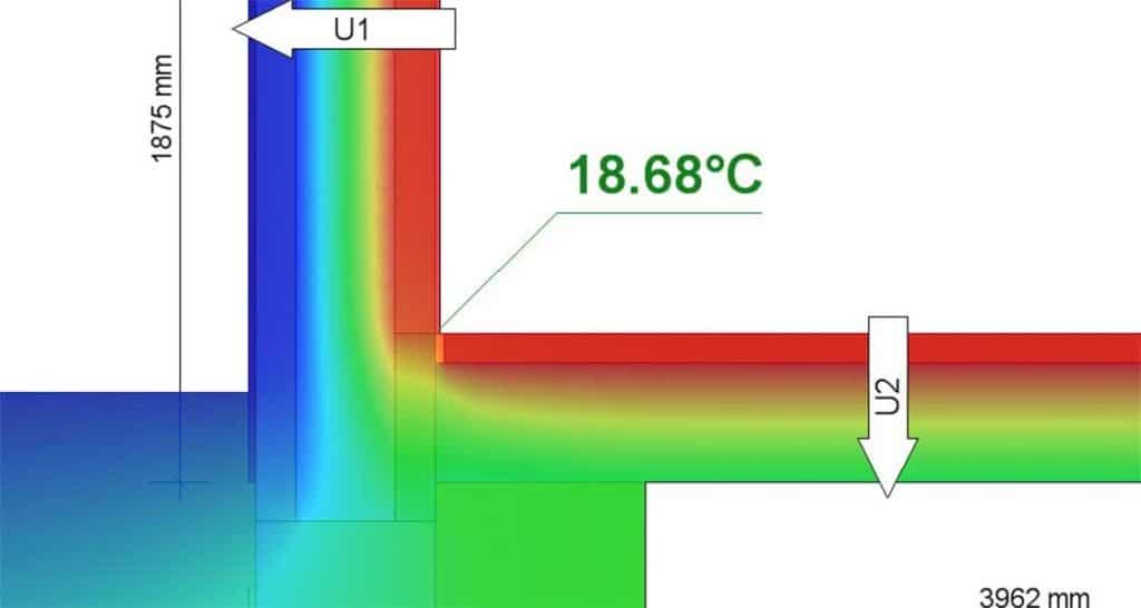
In most cases, thermal bridging is caused by insulation breaks, insufficient insulation, or when an element with higher thermal conductivity penetrates the insulation. What’s key to remember is that heat will always migrate to cooler areas through the path of least resistance (in this instance the bridge). Thus, when you heat your home, especially in the winter, heat will move towards the cold outdoors far more easily through weak points such as thermal bridges, causing energy and money to be wasted.
Approved Document L building regulations state that building fabric should always be constructed to limit thermal bridging, including at the party wall.
The guidance states:
“The building fabric should be constructed so that there are no reasonably avoidable thermal bridges in the insulation layers caused by gaps within the various elements, at the joints between elements and at the edges of elements such as those around window and door openings.”
Limiting Thermal Bridging
Approved Document L 2021 of England’s building regulations recommends the following thermal bridging solutions to help limit thermal bridging within buildings:
- Drawings
These should be provided for junctions and reviewed by both the designer and the installer to confirm their buildability and to ensure that the construction sequencing is carefully considered. Additionally, where possible, complex details should be avoided.
- Onsite audit
This needs to be performed in order to confirm that the designed details have been effectively constructed before the elements are concealed over. It is recommended that photographs be taken of the details in order to provide evidence of compliance to regulations.
- Product substitution
If a product which the design is based upon is substituted, the revised specification should be shown in the SAP calculation. It should also be highlighted in the BREL report. Changes to the specification after the design stage should be assessed for the impact on thermal bridging.
- Foundations
Any blocks that are below the damp proof course need to match those which were specified in the design, where applicable, for the above ground main wall element. Thermal blocks are also an effective solution for tackling the external wall to ground floor junction.
- Ground floors and external walls
It is recommended that all wall to floor junctions be detailed to achieve insulation continuity. For example, perimeter floor insulation needs to abut or extend the main floor insulation’s full depth according to the design.
- Intermediate floors
The regulations state that floor to wall junctions should be detailed in order to ensure that the external wall insulation is continuous. When the intermediate floor structure breaches the external wall insulation, further insulation will need to be included in the intermediate floor structure’s depth. This should have an equivalent thickness to the insulation used in the external wall.
- Windows
Designs which reduce thermal bridging should be selected. For example, consider making use of independent lintels with insulated cavity closure between inner and outer lintels. Additionally, insulated cavity closers ought to be used for all kinds of construction types. Furthermore, it is recommended that insulated plasterboard be used in reveals to abut jambs and this should also be considered within reveal soffits.
- Roofs
The guidance states that there should be continuity of insulation at the wall to eaves and the wall to gable junctions. It is advised that wall insulation be fitted to the top of the wall plate. Roof insulation should always be continuous with the wall insulation. This can be enabled in the design of roof trusses and roof cassettes.
How to Assess Thermal Bridging in SAP Calculations
It is important for thermal bridges to be assessed. When undergoing thermal bridge assessments in a new dwelling, one of the following processes should be used:
- Use construction details specific to the design and specification of the project and ensure that they are calculated by a suitably competent person with careful consideration of the guidance in the Building Research Establishment’s BR 497. The temperature factors outlined in the Building Research Establishment’s Information Paper 1/06 should also be followed.
- Make use of junction details from a reputable non-government database which contains independently assessed thermal junction details.
- Make use of the ‘default’ values which are highlighted in the Standard Assessment[JW1] Procedure, Table K1. Please note, a mixture of known and default values can be utilised. Using default values will however be detrimental to the overall performance of the building within the assessment. Bespoke/known values should be targeted.
- Utilise a default 0.20 W/(m2.K) Y-value, however this will again be detrimental to the performance of the building.
Off-Site Manufacturing – A Solution to Thermal Bridging
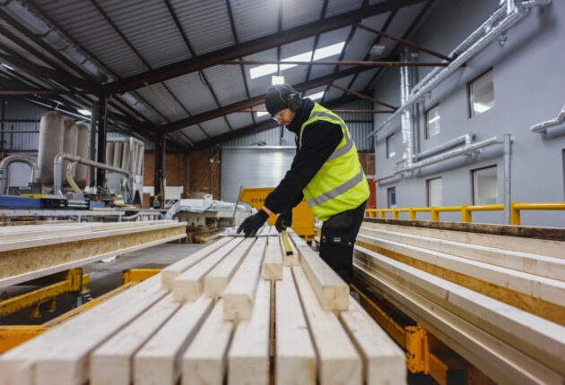
With off site manufacturing in factory controlled conditions, the ability to achieve higher tolerances with less With offsite manufacturing in factory controlled conditions, the ability to achieve higher tolerances with less margin of error is well proven. This repeatability and predictability is especially important in medium to high volume developments, or where build to completion times are critical.
In addition, there are a number of different options to choose from, each with its own advantages according to developer/client requirement and the type of building.
For example, trussed rafters have already overtaken solid timber roof construction to become the default ‘industry standard’. Meanwhile, the latest techniques in roof cassettes and panelised systems are opening up new design and space opportunities.
This particularly applies to ‘room in the roof’ or ‘attic’ solutions, which are increasingly popular with both homebuyers and developers. Given the shrinking footprint of the modern house, the ability to economically create extra habitable space is important in creating buyer appeal in the private market. Additionally, this makes the house more adaptable to different family sizes in the social or private landlord sector.
With proven solutions including vertical and horizontal cassettes, virtually every house design can be accommodated with a safe, easy to install, high performance roof structure.
As the leader in engineered timber roof and floor solutions, Pasquill’s technical services team can provide high level support and design solutions to assist customers make the right choice and help to meet the increasingly stringent requirements of Approved Document L, BREEAM, LEED, HQM and Passivhaus. Get a personalised quote for your project today.

